Marzocchi AG Strada

Two or three years ago I was lucky to find a set of new old stock Marzocchi AG Strada shocks factory set up for a BMW R100.  The original owner said he’d ridden them for about 100 miles and then put them on a shelf for over 20 years.  I bought them and helped the kind seller to clean out his closet.

I wanted to ensure that the seals were in good shape so I found rebuild kits from a source in Australia, and had my professional suspension technician rebuild them.  It turns out that the original seals were in fine shape.

I had read that these shocks were quite stiff.  As I weigh about 250 pounds, these shocks worked out perfectly for me.  There are 4 damping settings that can be set internally – and my set came at the highest setting.  There is a sticker around the Schrader valve that indicated the damping setting.
Marzocchi topThe seller provided me two original document booklets – the Owner’s Manual and Maintenance Guide, and a Parts Book.  I’ve copied them, and made them available here to help other owners of these classic shocks.

Marzocchi AG. Strada Instruction Manual

Click Here To Display Manual

Marzocchi AG. Strada Parts Manual

Click Here To Display Manual

Substitutes For Bosch Grease

Several months ago I overhauled the ignition sensor canister “bean can” on my 1984 BMW R100RS.  I describe that process in a seperate entry in this blog – available HERE.  Robert Fleischer’s excellent web site has an article reporting that the grease for this unit’s bearing is Bosch  FT1-V22 or FT1-V26.  You can read Fleicher’s article HERE.

BMW’S OEM shop manual also lists this grease for this application – listed as “Bearing journal for centrifugal advance.”  It specifies Bosh Grease FT1-V26.

Internet searches reveal that Bosh greases have new part numbers – FT1-V4 for distributer cam lobes is also referred to as 5-700-002-005.  FT1-V26 is 5-700-005-005.

I was able to find quite a few references to 5-700-002-005, and was even able to purchase a (large) tube of Bosh grease with the original label FT1-V4.  Unfortunately, as my motorcycle has electronic ignition, I don’t have a need for it.  I found no datasheets for any Bosch greases.

Without a datasheet, it’s difficult to identify a proper substitute.  The closest to a substitute recommendation I found is a German language forum in Europe where one fellow suggests a substitute for FT1-V22 with a different grease found on eBay.  The message thread is HERE.  Unfortunately, this substitute product is unavailable for shipping to the USA.  And I couldn’t find this product anywhere else.

Without an known substitute to Bosch FT1-V22 or Bosch FT1-V26, I elected to use BMW’s “wheel bearing and small parts” grease when I overhauled my ignition sensor canister.  (BMW part number: 82000419622)  The datasheet for this grease lists a “upper service temperature” of 284F.  The datasheet for this grease can be viewed HERE.  It seemed like it was a safe bet for this application.  I learned that this was a mistake.

I experienced no trouble riding the motorcycle about 2,000 miles after this ignition sensor canister overhaul.  However the engine quit from apparent ignition failure when running in my garage for about 20 minutes.  (I was conducting a test of battery voltages at various RPMs with my headed riding gear connected and on.)

I suspected the hall effect sensor in the ignition canister had failed due to excessive heat – not unlikely due to its age.  I ordered a replacement, but before installing it I wanted to see if the failure would repeat.  And I wanted to know what the motorcycle’s temperatures were leading up to the failure.

I removed the front lower fairing panel and the front engine cover, and conducted a test of temperatures at four points using an infrared thermometer.  After starting the cold engine in 51F ambient temperature, recorded the temperature every 2 minutes at the exhaust flange nut, the cylinder cooling fins, the oil cooler and the ignition sensor canister.  After 29 minutes the engine again stopped due to apparent ignition failure.

The recorded temperatures are displayed in this graph:


At 29 minutes the ignition sensor canister exceeded 300F.  I decided to compare this to the operating temperature range in the hall effect sensor’s datasheets.  Fleischer’s article on ignition lists the hall sensor to be either a Honeywell 2AV54 or a Siemens HKZ101.  Fleischer’s article is available HERE.

The data sheets for both these hall effect sensors show that 300F exceeds the operating limitation of both devices.  Links to these datasheets are here:

Honeywell 2AV54 Datasheet

Siemens HZK101 Datasheet

The datasheet report the hall sensor’s operating temperatures of up to 150C to 160C – which converts to about 300F to 320F.  This suggests that my motorcycle’s hall sensor failed due to being over temperature, and may not have failed due to age or other malfunction.

According to it’s datasheet, at 300F the ignition canister temperature exceeds the BMW grease’s 284F upper service limit.  I don’t know if grease failure contributed to the high temperature of the ignition canister, but regardless, the BMW grease left no margin of safety.  I disassembled the ignition canister and found evidence that the BMW grease had liquified.

The only other possibility for a substitute grease on my shelf is MOTUL Tech Grease 300.  It’s datasheet lists a temperature limit of 302F and a peak temperature of 428F.  It’s datasheet is available HERE.  This would have been a better choice than the BMW grease I had used.  But something with an even higher temperature limit would be even better.

The problem for me choosing a grease substitute is that I’m not knowledgeable about grease applicability.  I found an informative message thread about this particular issue HERE.

I discovered an application chart for a line of grease products made by Dow Corning that offers some help. The chart (available HERE) lists Dow Corning Molykote grease products by application (gears, ball bearing, busings, etc.) and information about the specific properties, limitations and example usages of each product.

Molykote BG 20 High Performance Synthetic Grease is listed as a general purpose synthetic grease for metal-to-metal plain metal bearings, bushings and sleeves. It’s temperature range is -50F to 360F.

Molykote 44 High Temperature Bearing Grease is listed as a high temperature grease with an operating range of -40F to 400F.

Both these products are available on eBay and other vendors for about $25 for a 150 gram tube.  I ordered one tube of each from Motion Industries.

Remote Fuse Panel Installation

This post describes the installation of a Centech AP-2 auxiliary fuse panel on my ’84 R100RS.  This fuse panel has two separate busses, allowing for both switched and un-switched connections.  For information about the Centech AP-2 click here.

I chose the Centech AP-2 because of it’s simplicity and because of it’s rugged construction – both consistent with this motorcycle.  There are few mounting locations available that provide accessibility,  weather protection, and no requirement to modify the motorcycle frame or bodywork.  The position I choose was a compromise.  It provides good accessibility and no requirement to modify the motorcycle.  However it isn’t well protected from weather, and may need something to protect it from the elements.

I mounted the fuse panel to the left side of the battery’s hold down frame.  I made a bracket by cutting out two rectangular pieces of sheet aluminum with four mounting holes that would attach to the hold down by sandwiching the diagonal piece of the hold down frame.

I decided to try applying a rubberized coating to the bracket pieces by dipping them in Plasti Dip.  The shape of bracket pieces made getting a smooth surface more difficult than I anticipated.  The coating was too thick and dripped away leaving lumpy streaks.  I ended up painting on the coating with the bracket pieces laying flat.  It would have been easier if I had thinned the Plasti Dip solution with one of the recommended thinners.  Unfortunately, I didn’t have any of the recommend thinners handy.

The back side of the AP-2 has exposed circuit board traces. I insulated them by applying several thick coats of Liquid Tape.

This mounting location resulted in a clearance problem. The upper rear corner of the fuse panel was too close to the motorcycle frame.  I was able to shift the bracket forward about 5 millimeters by cutting a notch in the inner bracket allowing it to clear the lip of the battery frame.

To trigger the relay for the switched circuits, I used a posi-tap to access the tail light circuit.  This excellent location was suggested to me by Anton Largiader.

Jim Wilson sent me photographs of an beautifully crafted plastic box he made for mounting a fuse panel on his motorcycle.  My mounting location doesn’t have enough clearance for such a box – hence the AP-2 on my motorcycle is exposed to the weather.  It may be that spraying the panel occasionally with WD-40 or Deoxit may protect it adequately.  If not, I may have to revisit this mounting location.

Charging System Tune-Up

This post describes my work inspecting and renovating the charging system on my ’84 R100RS.  The project falls short of an overhaul because only rudimentary testing and inspection was performed.  Indeed, this project is more in the category of “preventative maintenance.”  The diode board and voltage regulator seemed to have been working normally, but I replaced both as a precaution due to their age.  Where easily accessible, wires and cables were replaced for the same reason – although some appeared to have experienced heat stress or corrosion.  A great deal of thought was put into diode board mounts and grounding.  I hope my efforts result in continued trouble-free operation on the cross-country trips I have planned.

A Little Background

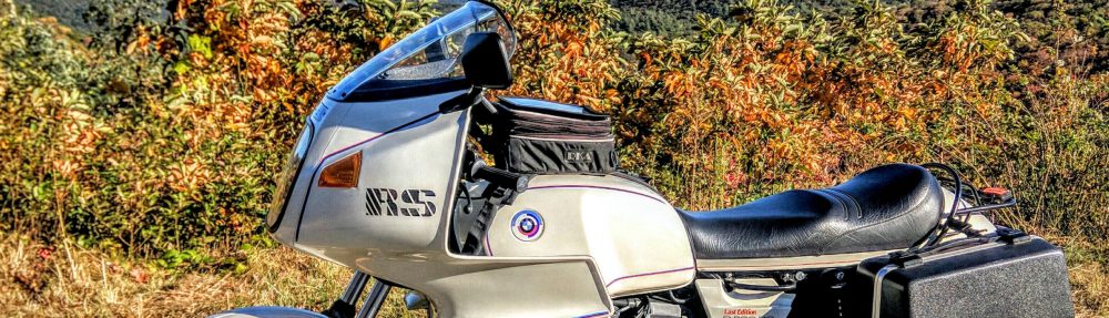
My experience with this motorcycle’s charging system goes back over 30 years ago when I bought a new ’84 R100RS from a BMW dealer in Walnut Creek, California. Within the first few years of ownership I replaced the diode board two times. The diode boards malfunctioned because solder melted out of them.  The ’84 R100RS in this project is one I purchased 3 years ago from Mary and Perry Bushong in Fort Worth, Texas.  It’s identical to the one I bought new in 1984 – both are “Last Editions.”

After the second diode board replacement on my new R100RS, the dealer suggested I replace the front fairing with a “police” version.  The diode board sits behind the front engine cover and the “police” fairing allows much greater airflow for cooling the front of the engine.  I was told that the stock fairing on my R100RS provides less airflow because it was designed to work with the addition of the new oil cooler intended to manage engine temperatures.

  • LEFT – “Police” front fairing
  • RIGHT – Original ’84 R100RS fairing

While conducting research for this project I found a BMW Service Information Bulletin that documents BMW’s acknowledgment that motorcycles were delivered with defective diode boards.  The bulletin authorized replacements under warranty. It seems I paid for at least one diode board replacement unnecessarily back in the 80’s.  After installing my second replacement diode board and installing a “police” fairing, my diode board never failed again.  I don’t know if the better cooling of the more open fairing or if the improved diode board resolved my problem.

The Scope Of This Project

I bought my “new to me” ’84 R100RS with the “police” fairing installed.  Luckily the previous owners kept it and passed along the original fairing to me.  In addition to ensuring that the charging system does a good job of keeping the battery charged, I hope to have the diode board working well enough to use the original fairing again – even if I can only use it in cold weather.

This tune up project includes:

  1. Installing a new OEM diode board
  2. Installing new OEM rubber diode board mounts
  3. Making and installing new diode board grounding wires
  4. Installing new alternator and diode board wires
  5. Inspecting the alternator brushes for wear
  6. Measuring the resistance across the armature rings for faults
  7. Installing a new voltage regulator
  8. Installing new battery cables
  9. Inspecting and cleaning the starter relay
  10. Replacing the engine breather hose

A comprehensive overhaul of the charging system would include more tests of the  alternator’s stator and armature.  Since the charging system is delivering a reliable 14 volts or so – I decided not to do those tests now.

Diode Board Mounts and Grounding Wires

Some years after I sold my first R100RS I began reading about new metal mounts for the R100 diode boards that cured their problems. The new metal mounts reportedly provide better electrical grounding and heat transfer than the OEM rubber mounts. They also have the advantage of never failing – eliminating the “pain in the ass” task of replacing a broken rubber mount.

After opening my engine’s front cover and removing the diode board I discovered that a previous owner installed two home-made metal diode board mounts. They were installed in the top two positions, grounding the diode board to the timing chest cover. The bottom two mounts were still OEM rubber mounts. The diode board’s two bottom mounting positions are electrically insulated and don’t benefit from grounding.  No diode board grounding wires were presently installed on this motorcycle.

  • LEFT – The two home-made metal mounts previously installed on my motorcycle
  • RIGHT – The four mounting positions on the timing chest cover

My research relied heavily on Robert Fleisher’s comprehensive article on Diode Boards and Grounding Wires. To read it: Click Here

Fleischer’s article has a partial history of the Service Information Bulletins pertaining BMW’s efforts to eliminate diode board failure. His article omits the first bulletin that authorizes dealers to replace owner’s diode boards with a newly manufactured version.  This bulletin also explains how to identify the new and improved diode boards by their different paint on the back of the circuit board.

Subsequent Service Information Bulletins provide instruction on grounding improvements for the diode board.  I presume that even the improved diode board would fail without improvements to the diode board’s grounding. None of the bulletins reference changing the front fairing to a “police” version. And none of the bulletins reference changing to metal diode board mounts.

The original diode board grounding design uses two fairly light gauge (I estimate 16 AWG) wires to ground the diode board to the timing chest cover – one to each of the two top mounts. The last Service Information Bulletin directs adding a new supplemental grounding wire.  Fleisher’s article refers to it as a “spider” wire.  The “spider” wire is also only about 14 or 16 AWG wire. It provides two additional ground wires, both to the engine case.  Additionally, it has a wire to ground the timing chest cover to the engine.

Both metal mounts and the original two grounding wires only ground the diode board to the timing chest cover.  This series R100 has a black coating on the timing chest cover that may affect its electrical conductivity to the engine.  The new “spider” wire adds grounding from the diode board directly to the engine.

My “new to me” R100RS had metal mounts but didn’t have any grounding wires.  Since the diode board hadn’t failed, any combination of things might be contributing to its success:

  • The timing chest cover may have good electrical conductivity to the engine.
  • The diode board may be one manufactured to withstand high temperatures.
  • The “police” fairing may be keeping the charging components adequately cool.

Another factor is that metal diode board mounts transfer heat and rubber mounts provide some heat insulation.  Robert Fleisher shared with me that he had measured diode board temperatures using a highly accurate thermocouple thermometer.  He did not share his specific results or testing conditions – but he fully supports using metal diode board mounts.  It seems counter intuitive to me that a diode board rectifying no more than 280 watts using appropriate wiring and connections would generate enough heat to achieve higher temperatures than the engine itself.

So whether the metal mounts allow heat to flow from the diode board to the engine or the rubber mounts insulate from heat moving from the engine to the diode board remains to be tested and reported by someone interested with a bit of time on their hands.  Frankly, I’d like to do this test myself.  The only other factor I can think that might be relevant to the diode board’s longevity is if the rubber mounts provide any significant vibration damping.

Because BMW never specified using metal diode board mounts, I decided to use four new OEM rubber mounts.  Many respected Airhead experts advise against this. (To the point of being described as “dogma.”)  This meant I had to use grounding wires.  I bought a complete set of OEM grounding wires but found the terminals poorly connected and made with light gauge wire.

Diode Board with OEM Ground Wires – Per the Last Service Information Bulletin

To ensure good diode board grounding I decided to make my own version of the “spider” wire using heavy 10 AWG wire and heavy .8mm brass ring terminals.  I also sealed the ends with waterproof heat-shrink tubing.

  • LEFT – The heavy .8mm brass ring terminals required using a vice to crimp.
  • RIGHT – The sealant from the waterproof heat-shrink tubing required a bit fo trimming to make the full surface area of the ring terminal available.

I connect one of my ground wires to the engine and the other to the timing chest cover – and a third wire grounds the timing chest cover to the engine.  This duplicates the function of the “spider” wire – but provides about twice the electrical load capacity over using all of the OEM ground wires.

  • LEFT – My 10 AWG grounding wires.
  • RIGHT – The grounding wire attachment points to the timing chest cover and the engine.

Inspecting and Replacing the Diode Board

A separate blog entry contains photos and descriptions of the diode board previously installed on my R100RS and the new OEM diode board I installed. To view it Click Here.

The diode board I removed shows no sign of heat stress other than some blistering of the paint coating the back of its circuit board.  I replaced the diode board with a new OEM part in the hope that improvements in the diode board’s components and manufacture might make it even more resilient to heat stress.

Removing and Replacing Diode Board Mounts – A Few Tips

One of the most common reasons I’ve read supporting metal diode board mounts is that they are unbreakable and never have to be replaced.  Removing and replacing lower diode board mounts in particular are said to be a very significant “PITA” or, pain in the ass.  In addition to figuring out how to get a wrench on the diode board mount’s nuts inside the timing chest cover, there was the fear of dropping nuts and washer into the timing chest.

Several tips make removal and replacing diode board mounts relatively easy.

  • Removing the breather hose and ignition sensor connection provides greater access to the right diode board mounts.
  • An 8mm flex-head ratcheting box wrench provides easy access to the rear diode board nuts.  The right lower nut can be reached through the front of the timing chest cover.
  • Tape on the wrench keeps the nut on the wrench until its threaded or after its removed.
  • Using “Whiz” nuts make using washers unnecessary.
  • There is a “shelf” on the back side of the timing chest cover that prohibits dropped fasteners from falling into the timing chest.  Dropped fasteners are easily retrieved with a magnet from the back side of the timing chest cover.  It is possible however to drop a fastener into the alternator housing.

New Wires

In addition to the diode board ground wires I made, I bought and installed new OEM wires connecting the diode board to the starter and the diode board to the alternator.  Two wires to the alternator and one wire to the diode board are part of the motorcycles wiring harness and appeared to be in satisfactory condition.  I cleaned their terminals with Caig Deoxit and reused them.

  • LEFT – old wires
  • CENTER – new wires and new diode board
  • RIGHT – finished installation

Measuring the Alternator Brushes

I bought new alternator brushes already mounted in the brush holder to avoid having to solder new brushes.  Soldering isn’t to challenging – this is just one place I’d rather avoid making a mistake.

I was prepared to remove the existing alternator brush housing but found I didn’t have a proper wrench to remove its fasteners without detaching the stator from the alternator housing.  So before tackling that, I decided to simply measure the brushes to see if they actually needed replacement.

Specifications on acceptable alternator brush length varied according to different references, so I elected to use the one that specified that the alternator brushes should be no less than half their original length.

Comparing the length of my new brushes to the existing ones showed I was nowhere near needing to replace them.

Testing Voltage Across Alternator Rotor Slip Rings

The factory service manual’s technical specifications list the resistance across the alternator rotor’s slip rings as 3.4 ohms,  +/- 0.34 ohms.

Testing mine with a digital volt-ohm meter I found mine to have 3.15 ohms – within spec.

Several other alternator tests are available.  The alternator brushes and the slip rings are readily accessible – and moving parts.  Since my alternator has been  working normally, I limited my tests to those items measuring the resistance across the slip rings.

Inspecting and Replacing the Voltage Regulator

I describe the original and new voltage regulator in a separate blog entry. Click Here to open that entry.

This motorcycle still had an original “metal can” electronic voltage regulator – which is adjustable.  I replaced it with a new non-adjustable plastic case voltage regulator simply because of the age of the original part.

Installing New Battery Cables

My research revealed that battery cables the age of this motorcycle can experience corrosion within the insulation by creeping inside through the cable over time from the exposed end of the cable.  For that reason I decided to replace both the positive and negative battery cables as a precaution.

Before installing the new cables I treated the exposed cable ends with Caig Deoxit and then sealed them with liquid electrical tape.

Inspecting and Cleaning the Starter Relay

From my reading, it seems possible that the starter and the headlight relays, along with the ignition switches, can malfunction causing problems with charging and starting. I had replaced this motorcycle’s headlight relay earlier, so I elected to simply clean and inspect the starter relay.  As nearly as I can tell, it works normally.  I cleaned the relay’s contacts and terminals and it’s socket’s terminals with Caig Deoxit.

What’s Next

This motorcycle still exhibits two things related to the charging system that may indicate faults I still need to investigate.

  1. The instrument panel voltmeter swings more widely when the turn signals operate than I believe may be normal.
  2. Even with the new headlight relay, the headlights to not appear to dim when activating the starter.  The starter has no difficulty starting the motorcycle – so that fault isn’t yet too worrisome. When cold weather comes in a few months, investigating this may be a higher priority.

Ignition Sensor Overhaul

This post describes the overhaul of the ignition sensor (bean can) of my ’84 R100RS.  The overhaul is accomplished in the following steps:

  1. Disassembly
  2. Cleaning
  3. Lubrication
  4. Installation of a new JPT connector
  5. Installation of new cork lining on the ignition sensor lid
  6. Reassembly

The sections about the installation of the new connector and cork lining are in separate posts. They can be viewed by scrolling down to them or clicking their links above.
Several other individuals have published information about their Ignition Sensor Overhauls – links to two of them are included here:

Note: The photos in George Turski’s post show an Ignition Sensor that’s slightly different than mine.  The flyweight’s on my Ignition Sensor have plastic parts attached at either end – and on one end that plastic also serves as a bushing for the pivot pin.  The flyweight’s in George Turski’s photos don’t have plastic – and that may effect their need for lubrication.  The photo’s in George Turski’s post also show an additional washer between the driven cog and the canister. There may be other differences – I know of no factory documentation or illustrations.

Disassembly

Step 1: Remove the spring around the pin in the driven cog.
Step 2: Place the ears of the driven cog in a vice or something similar so you can drive the pin out without damaging the bushings.

Step 3: Remove the washers under the cog for cleaning. There are two thin metal washers and a “fiber” washer between them.  In my case, the “fiber” washer appeared to be plastic with a very small waffle texture.
Step 4: Using a edged device (not too sharp), remove the plastic rivet from the electrical outlet. Then remove the three screws around the sides of the housing.

Step 5: Remove the two screws securing the lid, and remove the lid. I used a channel-lock pliers to grasp opposite sides of the lid and was able to remove the lid by gently pulling from either side.

Step 6: Remove the two screws securing the outer bushing bracket. Then using a pair of pliers grasp the tang on the large retaining clip and remove it from the housing.

Step 7: Prepare the shaft to be driven through the inner bushing by filing away any burrs around the hole for the pin that secured the cog.  There is a seal the shaft passes through and insuring that there are no burrs on the shaft may reduce the risk of damaging the seal.  Once smooth, tap the shaft through the bushing with a punch.

Step 8: Withdraw the shaft that holds the flyweights and hall sensor.  Be careful to loosen the electrical connection from the housing as it may stick.

Step 9: Remove the two washers on the shaft.  The “fiber” washer is the outer washer and touches the housing, the thin metal washer is the inner washer and touches the flyweight base plate.
Step 10: Remove the circlip and snap-ring from the shaft.

Step 11: The small pin securing the “umbrella” must be driven out.  The snap-ring below the umbrella must first be rotated so that its opening is aligned with the channel that the pin must pass along.  Then secure the flyweight base plate and drive the pin through to the inside.  Be careful not to lose the pin.

Step 12: Remove the snap-ring that is at the base of the umbrella and remove the hall sensor from the shaft.

Step 13: Remove the flyweight springs. Then remove the flyweight outer shaft. Find the small metal washer between these parts that may be sticking to either side.

Step 14: Remove the circlips from the flyweight pivot pins, and remove the flyweights. Note that there is a washer under each circlip seated around the flyweight’s plastic the plastic bushing.

Here’s the layout of all the parts I disassembled:

Cleaning

My favorite tool for cleaning small parts is a Dremel tool with a Scotch-Brite type attachment.  These come in two different levels of coarseness.  The ignition trigger housing has a smooth flat surface that mates to a fiber washer.  I cleaned it with the Dremel tool, but was unable to remove the small pitting on it’s surface.  The Scotch-Brite attachment was able to polish it to a mirror surface.  I don’t think the Scotch-Brite attachment should be used however on polished shafts or bushings. An assortment of Scotch-Brite pads, Q-Tips and soft cotton cloths were about the only other cleaning products I used.  Not knowing the sensitivity of the seal on the inner bushing, I was reluctant to use any solvents.

Lubrication

Robert Fleischer states that the perscribed lubricant for the ignition trigger’s ATU’s shaft is BOSCH FT1V26 (5-700-005-005) in his section on chemicals. He doesn’t specifically state that should also be used on the inner and outer bushings – but as FT1V26 is a bearing grease, I’d guess that was the grease to use.  I couldn’t find this grease for sale anywhere on-line – but from these photos, it does appear to have been available in the past.

There is a gap between the inner bushing and the seal that seemed appropriate to grease.
I applied a very thin wipe of grease on the outer bushing, and I applied a very thin wipe of grease between the flyweight outer shaft and main shaft. Both seemed appropriate.  The flyweights on my ignition sensor have plastic bushings for their pivot pins.  I’m not sure they need lubrication at all.  I did put a thin smear of grease on the pivot pins to help prevent corrosion – although I found no corrosion present on disassembly.  I put a thin smear of grease on the small washer between the flyweight outer shaft and the baseplate.  I didn’t apply grease on the large thin washers touching the fiber washers – nor on the fiber washers.
Various web sites mention using other lubricants for distributor shafts – from dielectric grease to Super Lube. Standard distributor cam grease is recommended by some.  Seeing how the ignition trigger mechanism worked, it seemed that almost no grease was needed at all – other than to maybe prevent corrosion.  There was very little friction on any of the components.
I decided on a “tip of the spear” choice of BMW’s “wheel bearing and small parts” grease. (BMW part number: 82000419622)  I found no reference to this grease’s use anywhere – so as far as I know, I’m the first person documenting its use for this application. According to it’s data sheet  this grease has a fairly high drop point of greater or equal to 220C – perhaps high enough for the airhead’s operating temperatures. I also found an old LUCAS reference to distributor lubrication. While LUCAS was surely the prince of darkness, it appears its distributor’s need for lubrication was not too severe.

Installation Of The New JPT Connector

click here

Installation Of New Cork Lining

click here

Re-assembly

Step 1: After lubricating the flyweight pivot pins and main shaft with a thin film of grease, reattach the flyweights on the pivot pins, place the flyweight outer shaft on the main shaft, and reattach the springs.
Step 2: Place the hall sensor onto the flyweight outer shaft, and install the snap-ring closest to it. Be sure to rotate the snap ring so the opening is away from the small pin channel so that it will not allow the small pin to pass past it.

Step 3: Place the flyweight baseplate on a secure place, set the umbrella on the flyweight outer shaft – seated against the inner snap-ring, and drive the small pin into the slot until it’s below the ridge for the outer snap-ring.

Step 4: Install the outer snap-ring on the flyweight outer shaft and the circlip on the main shaft.

Step 5: Place the then metal washer and then the fiber washer on the shaft and then insert the shaft through the inner bushing. Be sure that the mating surface for the fiber washer inside the housing is smooth and free of corrosion. I did not apply grease to this surface because I the fiber washers seemed to function properly dry.
Carefully seat the electrical connection into it’s slot. Re-attach the plastic pivot pin by simply pressing it in. Install the three screws on the outside of the housing that secure the hall sensor.

Step 6: Reinstall the large retaining clip and position it so that it will retain the electrical connection. After applying a thin layer of grease on the other bushing, install it with two screws. Then install the lid with two screws.

Step 7: Re-install the washers and driven cog. Re-insert the cog’s pin – being sure to secure the cog so that the force of driving the pin does not damage the outer bushing.  Re-install the spring over the pin.

Step 8: I installed a new o-ring on the housing, and smeared a bit of silicone grease on it to allow it to more easily seat into the engine.

Ignition Sensor Overhaul – New Connector Installation

This post describes my installation of a new connector on the ignition sensor (bean can) of my ’84 R100RS.

bean-can-dis-6aI disconnected my ignition sensor in order to move the wiring clear to make it easier to install a new diode board.  In this process, I discovered that the connector was cracked.  I had hoped I might simply repair the connector by sealing or gluing it, but as I handled the connector it began to crumble.  I removed the ignition sensor and disassembled it to get a better view to my best options for repair. It quickly became apparent that my best option was to overhaul the ignition trigger and install a new connector.
The first step was to identify this three-way male connector.  It’s called a “Junior Power Timer” or JPT. Additionally, its also sometimes prefixed as an AMP or BOSCH – perhaps because both manufacturers made versions of this connector.  A 2-way version of the JPT connector is used on some fuel injectors – such as the ones on my ’87 K100RS.
While not quite qualifying as “nerdy stuff” – here’s more than you might want to know about Timer connectors: Timer Product Overview
The female JPT connector has a wire clip that keeps the two halves securely together.  A newer style female connector has the wire clip designed for easier removal and installation – but is does make the connector somewhat bulkier. As the ignition sensor has a male connector, that difference doesn’t matter to me here.
After disassembling the ignition sensor I discovered that the wires from the connector were permanently affixed to the hall effect sensor.  My only choices were to either replace the entire hall effect sensor which typically comes with a new connector or remove and replace the connector.  It seemed easy enough to order and install a new connector – and much, much less expensive.
I bought a new connector from Euro Motoelectrics which came as package of both the male and female connectors.  While the new male connector connects perfectly to the old style female connector on my bike’s wiring harness, the rubber boot provided is wrong for this application.  It has openings for three wires.  A boot with a single opening would have been preferred.  I used “liquid electrical tape” to seal the two unused boot openings and the center opening.
bc-connector-parts
The first step was to record where each color wire was in the old connector. The second step was to remove the connector from the wiring.  This connector was permanently bonded to the wiring, so the easiest method to remove it was to simply crush it.
bc-crushed-connector-2bc-connector-three-old-terminalsI wanted to preserve as much wire length as possible, and considered prying open the crimps of the old terminals – but that proved too difficult.  So I simply cut off the old terminals, and cut away enough of the cable sheathing to allow the three wires to fit properly into the connector. It took two o-ring picks to hold the center opening of the boot to get the wire through it.
bc-connector-use-center-hole-2
Crimping on the new terminals was easy using a standard crimping tool.  It wasn’t too clear where the little yellow “boots” were suppose to go – they seemed to be designed to seal the wires as they exited the hosing of the connector, but these wires are too small to allow them to make an effective seal.  I decided to simply place them over the crimps – just to have a place to put them.
bc-connector-crimps-and-seals-2
The terminal’s retaining “barbs” easily clicked into place within the connector housing.
bc-connector-almost-finished-connector-2
After seating the boot over the connector, all that remained was to seal the openings on the boot with liquid tape.
bc-connector-finished-2bc-liquid-tape

Ignition Sensor Overhaul – New Cork Lining

This post describes the process I used to make a new cork lining for the ignition sensor (bean can) lid on my ’84 R100RS.

After removing the two retaining screws, the easiest way I found to remove the lid from the ignition sensor is to use channel-locks and gently pull away at opposite sides of the lid.

Inside the lid shows the original lining I assume is cork.  It shows deterioration and distortion and appears saturated in an oily substance.

The lining fits into the lid which is dished about two millimeters and extends to the outer lip of the lid – apparently serving as a gasket.

Polling others with previous experience I learned that some ignition sensors were not lined – or found to be unlined when serviced. Tom Cutter of Rubber Chicken Racing Garage mentioned using a remnant of Snap-On tool box drawer lining material to make new linings when he does ignition sensor overhauls. No one I spoke with seems to know for sure why the lid has a lining.

I measured the thickness of the lining to be about 1/32″ – and found cork material of that thickness to be readily available (amazon.com) for a few dollars.

After failing to make a good tracing of the lining to make a new template, I decided to do it by photographing it and printing it to scale.  Click this link to bring up the template I made.

To make the holes in the cork linking I used brass tubing to make two punches.  I sharpened the tubing edge with a file to make clean punch.  Because of the distortion of the old lining, there’s no way to know exactly how big to make the holes.  So I simply took the lid to the hardware store and found brass tubes that seemed about right.  Aluminum tubes would have worked just as well – but the store had brass.  Only a couple of dollars.

Because cork and metal are dissimilar materials, I decided to use rubber cement to glue the lining into the lid.  And when I removed the old lining, it left a residue that seemed like the original lining was attached with something similar.

Here’s the materials I used in making a new cork lining:


The paper template is a couple of millimeters too small because the lid is dished.  To make the right size cork disk I traced the lid on the cork with a Sharpie – and then cut around the outer edge of the black line.  That worked out to about the right size.

I then placed the paper template over the center of the disk, and used the brass tubes to punch holes in the proper places.  It seemed to work best when I used the mallet to start the punch and then rotate the tube to finish cutting through the cork.


Removing the old lining was very easy – it scraped away easily with my fingers.  I used my Dremel tool with a Scotch-Bright type attachment to clean away the residue and minor corrosion.

After cleaning the lid, I painted the cork and the lid with a thin layer of rubber cement using a small paint brush.  I slowly formed the cork into the dished inner surface of the lid.  Only a small amount at the outer edge required trimming.

Working slowly, the heat from my thumbs seemed to allow the cork to follow the surface of the lid with little difficulty.

Ignition Sensor – Disassembly

By now I’ve gotten used to one job leading to another as I work my way through refurbishing my ’84 R100RS.  Fixing an improperly installed drive shaft boot lead to new swing arm bearings and a new drive shaft to replace the u-joint.  Installing time-serts to repair stripped threads for the filler plugs on my bevel drive lead to a complete overhaul of the bevel drive. Installing a new rear tire lead to new taper bearings… The good news is that by the time I’m done, I’ll be pretty much familiar with every system on the bike – a key component of reliability for the long distance rides I have planned for this bike.

So I shouldn’t have been surprised as I disconnected the Ignition Sensor for easier access to install my new diode board that I found the ignition sensor connector was cracked.

This connector housing operates similarly to the ones connecting to the fuel injectors on my ’87 K100RS – it uses a wire clip to secure the male and female halves.

This connector crumbled as I cleaned it – thinking I could just glue it back together. Now it has to be replaced.  The connector appears bonded to the wire pigtail – so I decided to disassemble the ignition sensor “bean can” to see where I might best make the necessary replacement.  True to the “one thing leads to another” maxim – I’m now looking at an overhaul of the ignition sensor.  Probably not a bad idea given it’s age.

It took a while to figure out exactly what this connector is called – the most generic name I was able to find is “Junior Power Timer” or “JPT.”  While the connector on my bike was probably made by BOSCH, my GOOGLE searches seem to suggest that AMP (Amphenol) also makes this connector.  I found on-line vendors selling replacements for this plug describing it with various combinations of “Junior Power Timer”, JPT, BOSCH and AMP.

I reached out to the Airlist email list server for help, and was quickly guided to Euro Motoelectrics and Motorrad Elektrik.  Euro Motoelectrics (EME) had the part.  After already submitting an order with EME, Tom Cutter of Rubber Chicken Racing Garage also responded that he had this and other connectors available – and could even to the overhaul for me if needed.
Within hours of ordering the connector from EME – and got a personal response back from their Norman Schwab – on a Sunday!  What great service!  And since it’s Sunday – why aren’t these guys out riding?  Here’s what I ordered:

Euro Motoelectrics – ignition sensor connector

I managed to disassemble the ignition sensor with minimal difficulty.  It required using a punch and snap-ring pliers. I have the punch, but my snap-ring pliers were too large. I was still able to remove the snap-rings using o-ring picks.  This resulted in marring one of the shafts slightly – I’m hoping I can correct this with course scotch-brite and maybe a little buffing with my Dremel tool.

I found a fairly comprehensive tutorial about disassembling the ignition sensor on-line, but after scanning it, I decided I’d do as well just to go slow and work the puzzle on my own. Ignition Sensor Disassembly Tutorial

As far as I can tell, re-assembly ought to be fairly straight forward – especially after I buy a smaller snap-ring pliers. I’m guessing that proper cleaning and lubrication should be straightforward by avoiding solvents and using light clear grease.

The inside of the “bean can” cover is lined with 1/16″ cork which is deteriorating. Tom Cutter offered that he uses a light foam material to replace it – but 1/16″ sheet cork is available, so I might try that first. An Airlist message from Michael McPeak indicates that the cork lining may not have a function beyond sound deadening – and he’s seen some without a lining.  Close inspection of my part indicates that the cork extended to the lip of the cover, and also functioned as a gasket.  For that reason alone, I’ll probably try to use something.  Michaels McPeak’s message was encouraging – what a great group folks these Airhead enthusiasts are!

Parts is Parts

This table lists vendors who provided parts and excellent service to me on my various projects. Of course it’s only a partial list out of the vast number of excellent vendors – but it’s the ones I’ve had the opportunity to use so far.

VENDOR DESCRIPTION
MAX BMW
www.maxbmw.com
BMW Motorcycle dealership in New England with four locations. Excellent online ordering with OEM fiche enhanced with photos and technical information.
On a trip to Maine last year I dropped into two dealerships.  In North Hampton I got to meet Drew Batson and Rusty Gill.  Drew has handled most of my internet orders, and is very responsive to any special requests regarding availability and shipping.  Rusty Gill has been a great resource in researching the few questions that have surfaced about OEM parts.
In one of their two Conneticut locations I was impressed by the wall of beautiful parts drawrers – where their parts man found exactly the wiring harnes component I wanted for my R1200ST.
moto-bins
www.motobins.co.uk
BMW parts vendor in the UK with good pricing, availability and international shipping. Common OEM service and alternative parts for most BMW models.  I’ve had some trouble on how their website links to PayPal, but their sales staff responded quickly with a manual order via email.
Ted Porter’s Beemer Shop
www.beemershop.com
I’ve been amazed at the level of personal attention and service that Ted Porter has provided me. I’ve had both a bike serviced in his shop and ordered custom Wilbers shocks. Few do it better.
Spiegler Performance Parts
spieglerusa.com
Top quality stainless brake lines and other performance parts. Excellent customer service with very knowledgable and helpful staff.
BING Agency
www.bingcarburetor.com
This is the factory authorized franchise in the USA for OEM carburetor parts, upgrade parts and technical information. They’ve been very helpful with my telephone inquiries.
Northwoods Airheads
www.northwoodsairheads.com
Tools and parts for common BMW Airhead services. A good selection of upgrades and reproduction parts.
Duncan’s Beemers
www.duncansbeemers.com
An amazing assortment of used BMW motorcycle parts.  I had the pleasure of meeting Duncan at his shop – I was impressed by his inventory, knowledge and helpfulness.
Cycle Terminal
www.cycleterminal.com
A vast selection of hard to find electrical components. Fast and helpful service.
Eastern Beaver
easternbeaver.com
Excellent headlight relay kits. Many other electrical parts and tools. This vendor is in Japan, but is as easy to work with anyone domestic. Very responsive to technical inquiries.
Wiring Products
www.wiringproducts.com
Huge selection of wire and related products. My wire orders were custom packaged and labeled with my name and wire specifications. Impressive.
Clips And Fasteners
www.clipsand fasteners.com
When I needed longer 3mm screws to make it easier to install the clamps on the drive-shaft boot on my R100RS, this vender had exactly what I wanted – stainless with an allen head.
Mr Injector
www.mrinjector.us
I used this vendor to clean and calibrate the injectors on my K100RS.  I also purchased substitute injectors originally used on the Ford Ranger.  The owner was helpful with my technical questions and provided good parts and service.
Battery Mart
www.batterymart.com
I’ve had good luck with AGM batteries from this vendor. They offer a battery that is almost a perfect size match for the OEM BMW flooded battery. Free shipping and great prices.
Overseas Speedometer & Instrument Service
speedometer.com
When the speedometer in my ’84 R100RS striped a nylon gear, this fellow did a great job repairing it. I can’t remember how I found this vendor – I’ve seen almost no on-line references to this vendor.
Race Tech Suspension
www.racetech.com
After reading Paul Thede’s book, The Motorcycle Suspension Bible, I am much better informed about how to equip and set-up my bike’s suspensions.  I’ve also visited their factory, shop and warehouse in Los Angeles.
I’ve had great success with Race Tech “Gold Valve” cartridge emulators on my K100RS and other bikes with damping rod forks.
The Race Tech website allowed selecting proper spring rates to achieve correct sag for my weight.  The Race Tech website and tech support make it easy to find the right parts.
An article in Motorcycle Classics detailed Race Tech’s upgrade to the forks and sliders of an older Laverda. Similar to my K100RS, this Laverda’s sliders don’t have bronze bushings, and rely on metal to metal contact between the fork tube and slider. Race Tech had the sliders on their Laverda project hard annodized to reduce friction and stiction.  I’ve had them do the same on my K100RS and will likely do the same on my R100Rs.
RKA Luggage
www.rka-lugghage.com
Several years ago I had the pleasure of meeting Richard and Kathleen (the “R” and “K” in RKA) at their home while they were temporarily without a storefront. RKA is a big supporter of the BMW community – and had just the right tank bag for my new-to-me K100RS.  Richard was super helpful helping me get the bag installed – which as a newbie to the bike was very appreciated.
Twisted Throttle
www.twistedthrottle.com
I mention Twisted Throttle because I’m a fan of SW-Motech products and I’ve had good luck with them sourcing both SW-Motech and Givi products for R1200ST.  I hope to adapt an SW-Motch “ALU RACK” to my R100RS. Revzilla also sells SW-Motech products
BoxerWorks
www.boxerworks-service.com
Nathan Mende’s shop is always a beehive of activity – and it’s fun just to walk through and see what’s going on. There’s a treasure trove of used parts up in the attic – I bought a speedometer there to use while I was getting the one on my R100RS repaired.  I don’t know the mechanics presently working at BoxerWorks, but when Dean Graham was there, he did an excellent job overhauling my R100RS’s bevel drive and installing time-serts to repair striped threads on the filler plugs.
Blue Moon Cycles
www.bluemooncycle.com
This was my local go-to shop for OEM parts until they sold their dealership to Hourglass Cycles.  Its presently where Dean Graham works – so it’s likely to be my local go-to shop for jobs beyond my skill and experience.
Euro Motorelectrics
www.euromotoelectrics.com
This shop had just what I needed – a replacement plug for my ignition sensor. I got a quick response back on a Sunday!

While the list above is primarily a source for “products” – many vendors are sources of both parts and services.  I was forwarded these two links to lists of vendors who service to Airheads like my ’84 R100RS.
www.airheads.org – Airhead Capable Vendor List
ibmwr.org – Independent BMW Motorcycle Wrenches
Following #6 of the Airhead Club Cannons, I try to do as much work on my bikes as possible.  But I couldn’t succeed without some of the extraordinarily talented mechanics and their shops.

1984 R100RS Charging System Project

This post is a work in progress – it will be expanded and enhanced as the project proceeds.

I’ve owned this 1984 BMW R100RS about 3 years now – and put about 10,000 miles on it – the odometer now reads 45,000 miles.  In that time the charging system has never failed to keep the battery charged – both a flooded cell and later a AGM.

I owned this same year and model bike, a “Last Edition” back in the 1980’s – I bought one new.  That bike had 2 or 3 diode board failures due to solder melting out of the board.

This “new to me” bike has so far had no electrical system failures while I’ve owned it.  It does however have two indications of possible electrical faults – 1) The instrument panel voltmeter doesn’t go to a lower voltage in cruise – indicating that the voltage regulator isn’t correctly responding to the battery being fully charged. 2) The instrument panel voltmeter swings widely when operating the turn signals – indicating any number of possible faults.  Getting the charging system up to snuff reduces the possibilities and may make tracking that fault easier.
Dismantling the charging system components I discovered this bike had been modified by the addition of two home-made metal diode board mounts installed on the upper mounts.  (The bottom two mounts were original rubber mounts.)  The bike appeared to have an original or very old diode board, and had neither the original two diode board grounding wires, nor the addition of the “spider wire” grounding wire advised by Service Information Bulletin 12-019-93 (2611).

Proper diode board grounding is an essential part of preventing diode board failure.  As such, the home-made metal mounts on my bike appear to have done a fair job of grounding the diode board to the timing chain chest cover.  Presumably, the timing chain chest cover has fair grounding to the engine itself.

After some effort getting up to speed on airhead charging system problem and remedies, I’ve settled on the following plan:

  • Replace the diode board with a new OEM part.
  • Replace the voltage regulator with a new OEM part.
  • Replace the alternator brushes. (entire holder assembly)
  • Replace the wires attached to the diode board and alternator not part of the motorcycles main wiring harness.
  • Install the two original diode board ground wires.
  • Install the additional diode board ground wires. (spider wire)
  • Install four new OEM rubber diode board mounts.

Most opinions voiced among the airhead community advocate the use of aftermarket metal diode board mounts. After seeing the flimsy nature of the OEM diode board grounding wires, I can see why.  The OEM grounding wires that I purchased for this job are both poorly made and use light gauge wire.  I suspect they are inadequate at grounding the diode board – particularly at periods of peak power output.

The other issue about diode board mounts is heat transfer.  I’ve heard of people conducting tests that support the notion that metal mounts transfer heat away from the diode board to the timing chain chest cover.  I’ve not however reviewed any data confirming these tests.  My gut instinct is that a properly grounded and connected diode board operates at a lower temperature than the timing chain chest cover in operation.  As such, the OEM rubber diode board mounts would provide some amount of insulation of heat transfer from the engine to the diode board.

Adding to this gut feeling is that after numerous Service Information Bulletins to fix problems with diode board failures, BMW never advised using metal mounts on my particular model – as used on some other airhead models.  I’ve not read or heard anything other than conjecture about why BMW never advised changing diode board mounts for my bike.
It’s been noted that rubber mounts will eventual fail due to age.  I agree that metal mounts are immune to this problem – but the two rubber mounts on my bike are in in good shape, and may be original to the bike – 30 years old.  Replacing them now ought to provide good service for my remaining riding years.

The photo below shows the parts I’ve assembled for this project:
Examining the two OEM ground wires (shown below the diode board in the photo above) I discovered that the ring terminals were poorly crimped, and made with surprisingly light gauge wire.  I decided to make replacement ground wires using heavier (14 AWG) wire and solid brass ring terminals.

This photo below shows a close up of the two OEM ground wires and the first of the two I’ve made to replace them.

I’m considering upgrading the 4-terminal “spider wire” in a similar way.
To be continued…